HW1. Parametric Michell Truss Structure. FEM.
Files to download
GrasshopperAssignment
a_ Parametric Framework
We were asked to start playing (higly recommended) with Rhino and Grasshopper in order to generate a parametrized Michell Structure as a function of L (distance from the origin to the farest point of the structure in the X axis, in feets), H (vertical distance between Pins, in feets) and Number of elements in the structure. As there is no direct analytical model that can solve the geometrical places of all elements, the workflow I have done is:
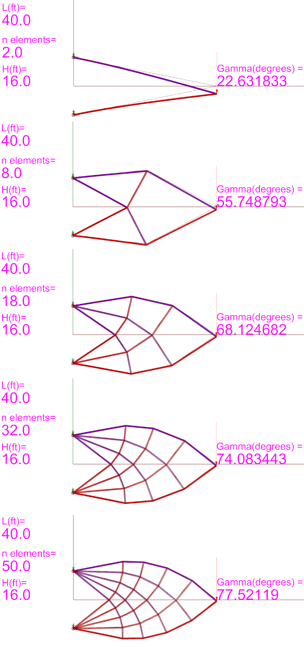
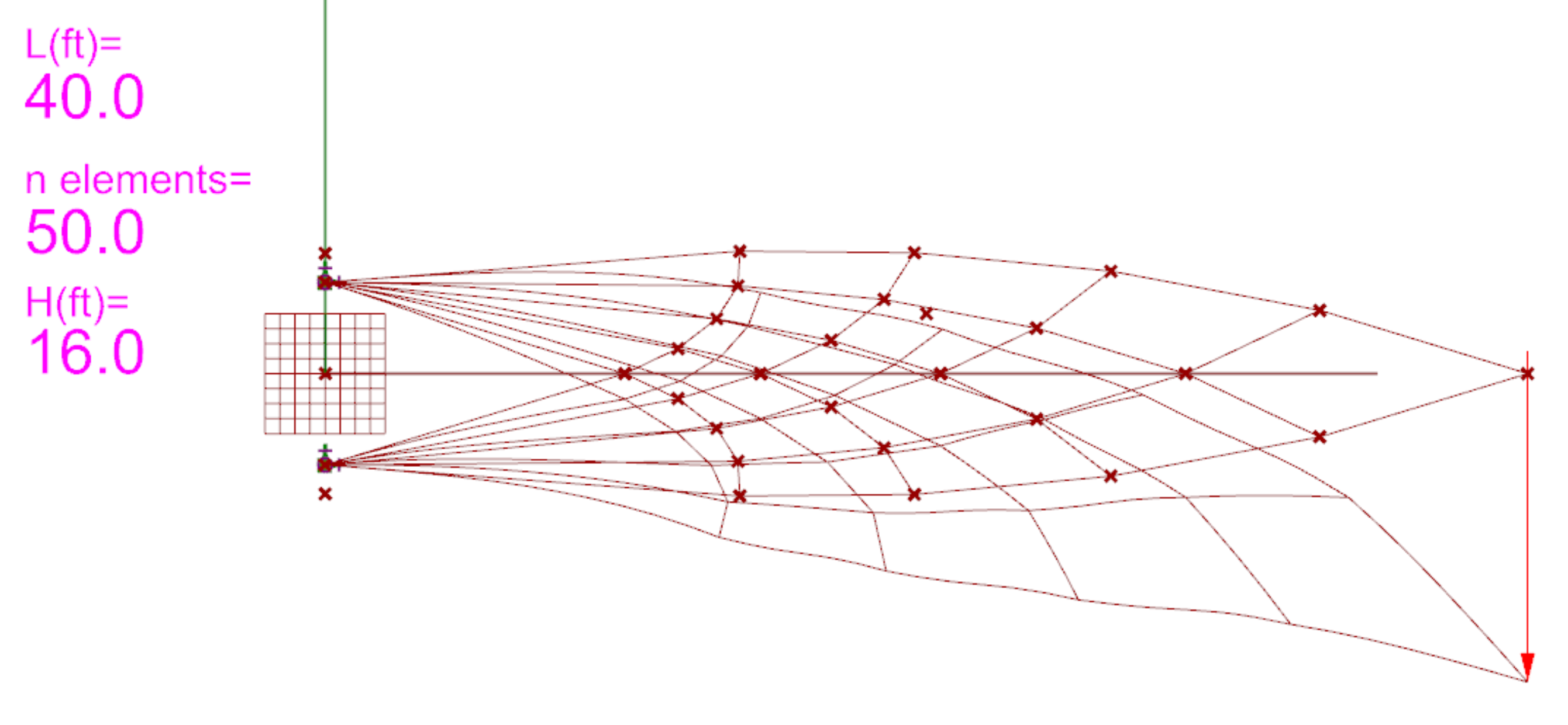
The following set of images shows all the 15 cases asked to compute. This images correspond to the firs question of the Homework but also adds a FEM analysis in which the displacement can be seen. Also, the line structure can be seen in red below. The value of Gamma is computed in the same point in which the load is applied.
Values for h = 16 ft
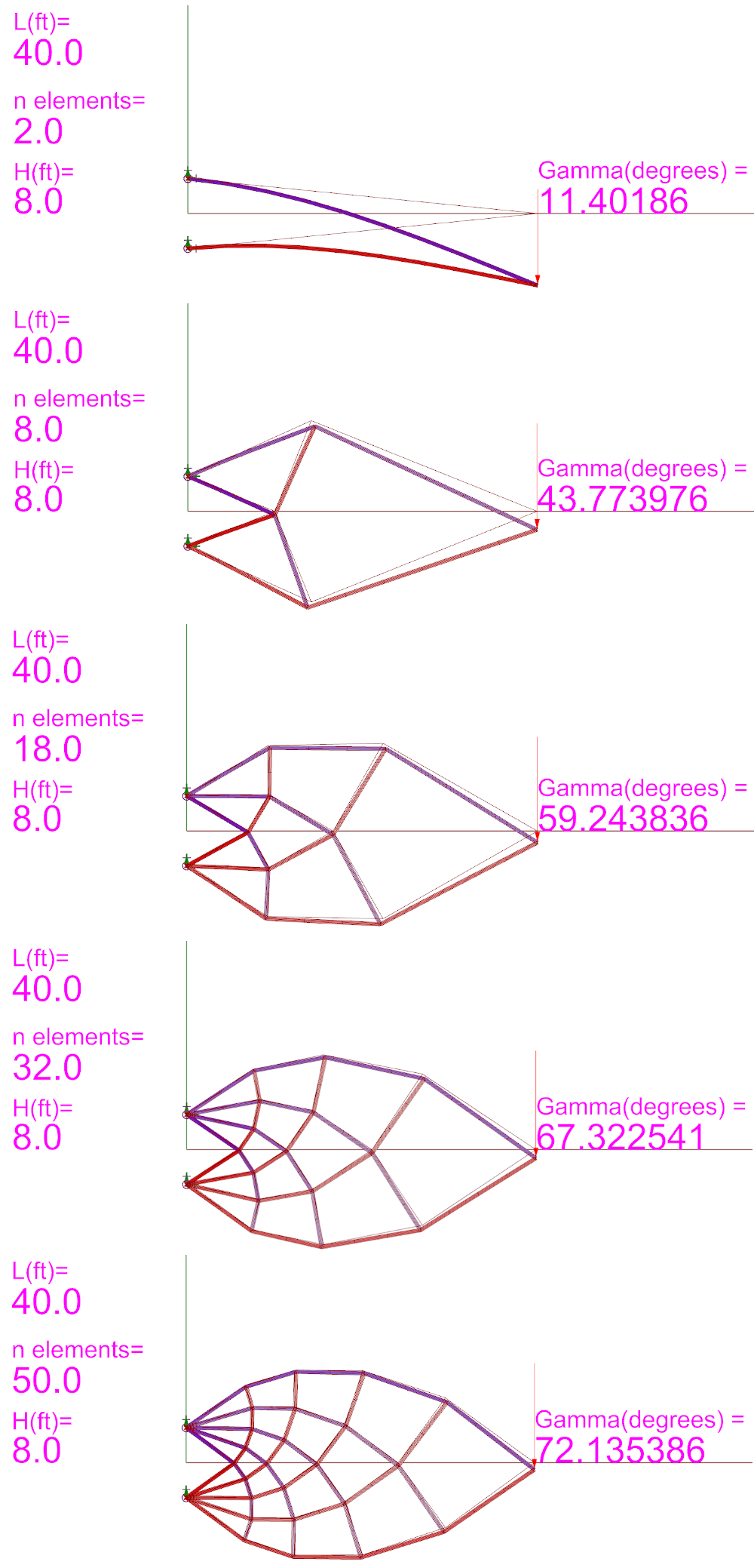
Values for h = 8 ft
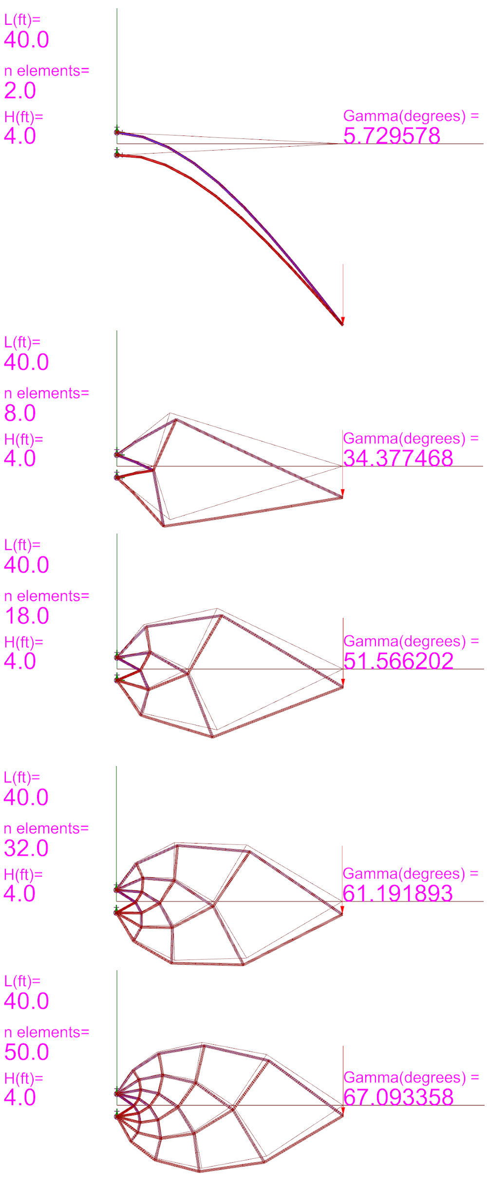
Values for h = 4 ft
b_ Analysis
On the previous images it can be seeing the FEM analysis that were applied with Karamba in the 3d structure to obtain the normal forces in every bar. By using the tools Dissasemble and Beam Resultant Forces, it is possible to obtain two list of important information.
First, we obtain a list able to plot for any N value, the length of the bars. In a second place, with the Beam Resultant Forces Modulus we obtain the list of the normal forces in every element. We are going to compute the absolute vlue of the summation of the product of each length and its force in each bar for all the previous 15 cases.
The applied load has been very large, 1000kpis in the axis Y with direction [0,-1,0]
For the question What patterns do you notice related to the forces in the members? the answer is the following
As it can be seen in the images posted below, there is an interesting behavior of how the layers of the michell structure behaves. All longitudinal lines of beams which starts in the pin above the load works in tension. On the other hand, all layers of beams that start in the pin below the load, works in compression. Also, it can be seen that the load density decreases in all beams when more elements appears in the truss structure.
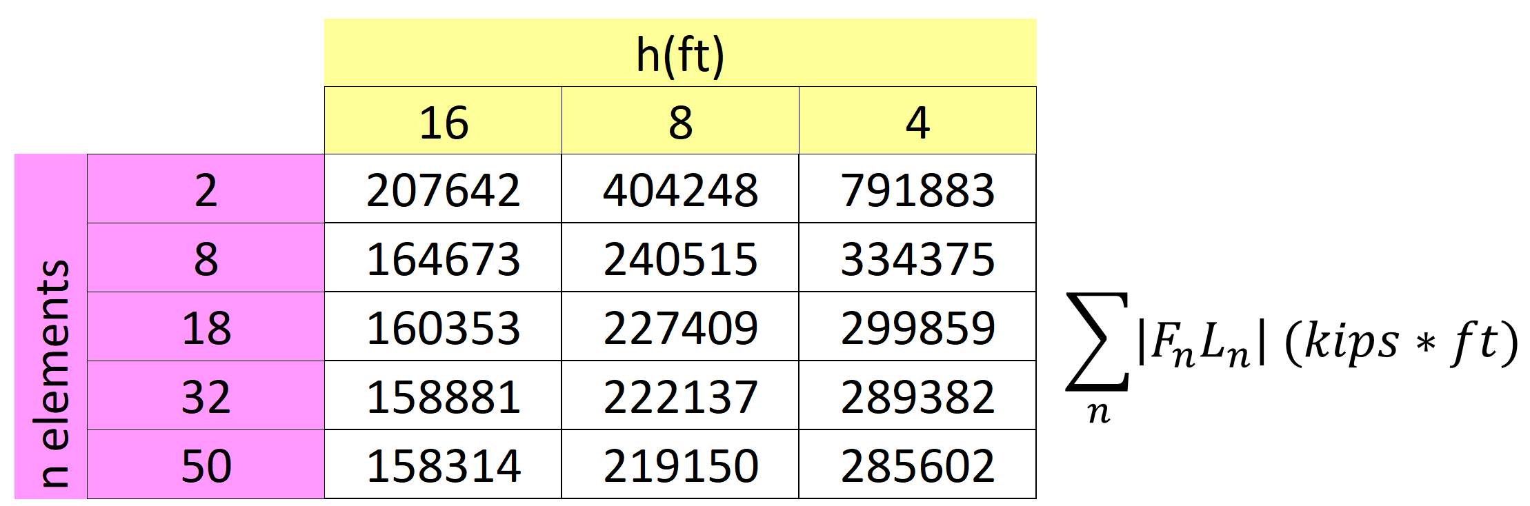
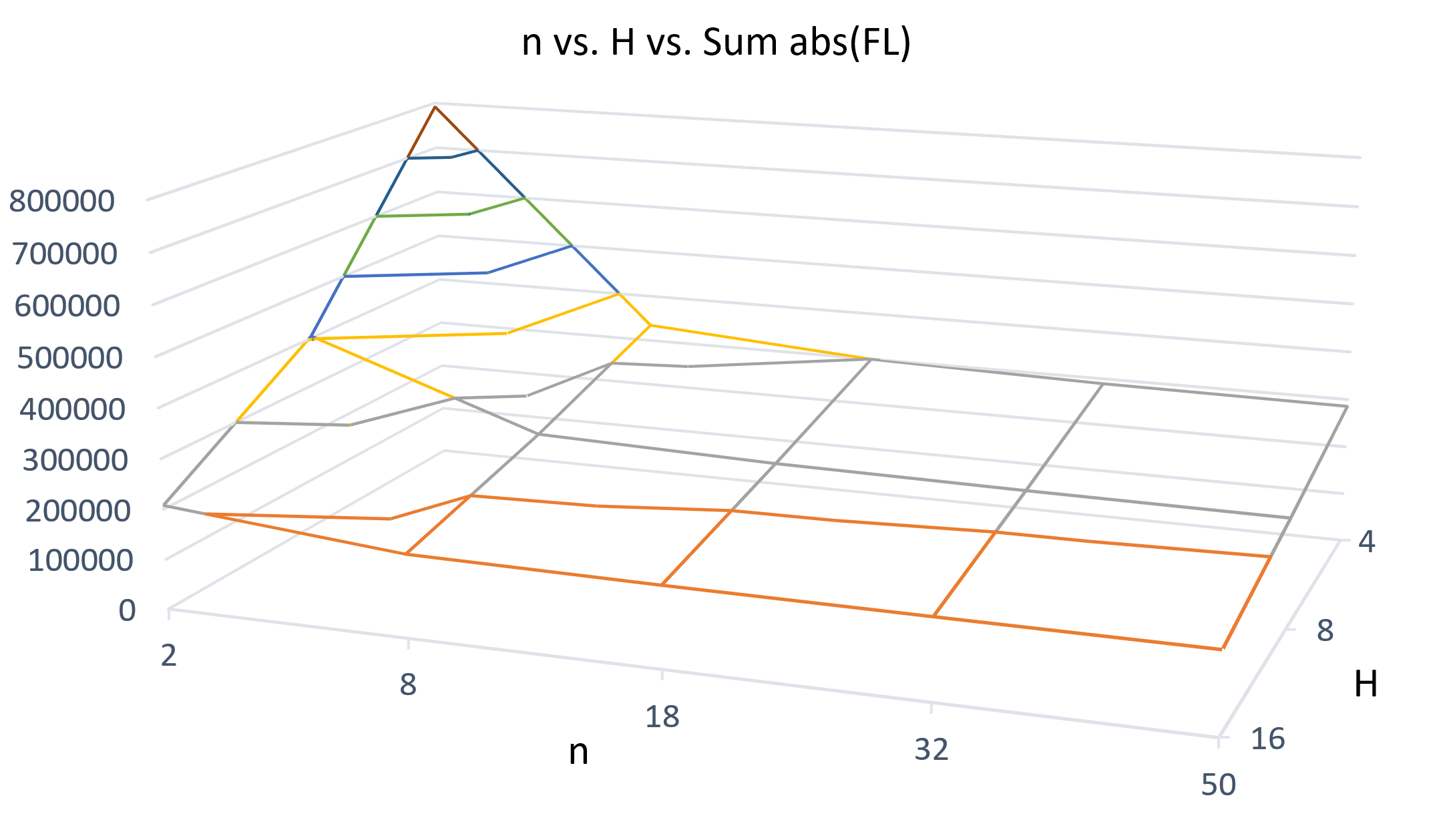
What it can be seen is that as more elements in the michell structure, the tendency of the load per length decreases reaching a local minimun at h=16, n=50 inside this 15 cases. Also, it can be seen that as higher H, a better resistance the structure will have with the momentum that the load apply to the structure. There is no visual convex or concave shapes in this mesh and also it can be seen a constant slope in this plane. It is correct to think that as we increases n and h the value will be smaller. We need more data to know if there is a certain point in which by increasing n and h the value of the product start increasing again.
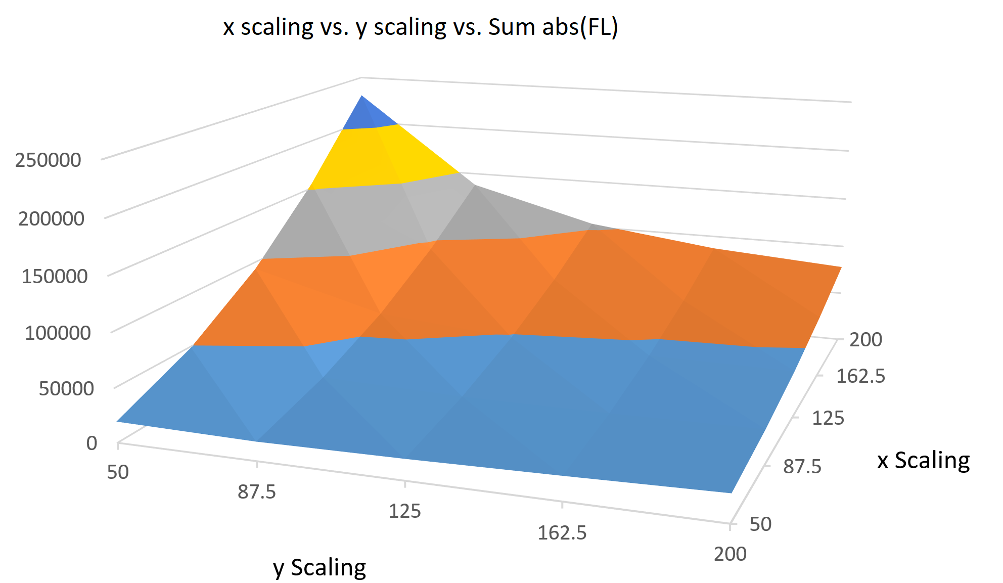
c_ Scaling
A new module in the grasshopper file has been inserted and now there is a FEM calculation for the scaled structure
Scaled FEM MihellHere is the chart obtained by meassuring the proposed 25 scenarios of different scaling values in each axis.
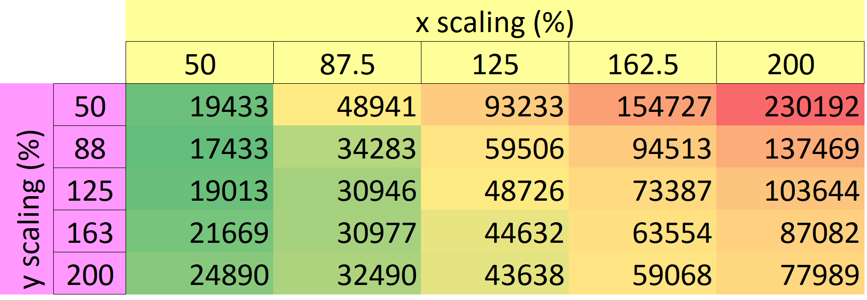
Inside this iteration, it can be seen how we are finding zones of the mesh that changes the slope. MAybe we are not finding a minimun but definitely we are finding a valley. Taking into account that the force is applied on the Y axis, by increasing the x axis we are increasing the deflection of the structure with the same load. The curious case is that for a fixed x value, by increasing the y axis, the structure start behaving better until a point in which the mass plays a bigger role than the force, so the value start being increased again.
Also we can not find here any minimun so there is not a cleas conclusion in this graph
the onli clear conclussion is that scaling this structure to make it more slender to look like a building, for the case of a lateral force in the tip, we are making the stucture weaker, compared with the original value.
In my opinion, the performance loss is so significant (almost a 50% by increasing a 33.7% in the x axis)